
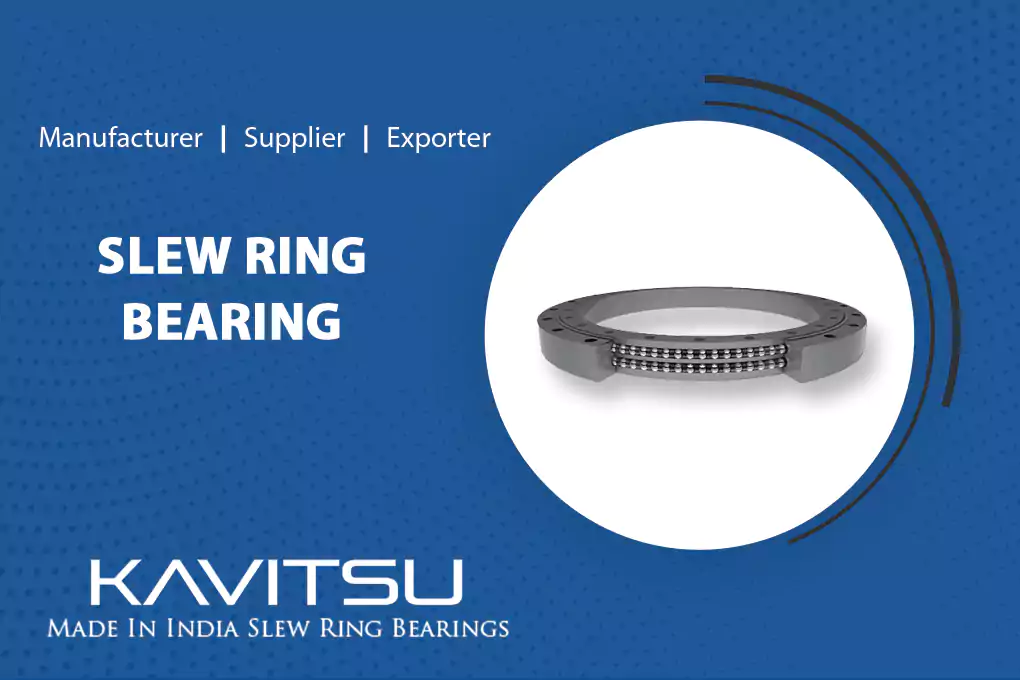
Correct installation is one of the most critical factors in determining the service life of a slew ring bearing. A high-quality bearing incorrectly installed can fail within months — while a correctly installed bearing will deliver its full designed service life of 10–25 years.
This step-by-step guide covers the complete slew ring bearing installation process — from pre-installation inspection through to run-in procedure. It applies to single-row ball, double-row ball and three-row roller slewing bearings in cranes, excavators, industrial turntables and other heavy machinery.
⚠ Safety first: Slewing ring bearings are heavy precision components. Always use appropriate lifting equipment. Never drop or impact the bearing. Keep all personnel clear during machine operation after installation.
Tools and Equipment Required
- Calibrated torque wrench (range matching the specified bolt torque)
- Dial gauge and magnetic stand — for flatness and backlash measurement
- Straightedge or precision spirit level — for surface flatness check
- Feeler gauges — for backlash measurement if dial gauge unavailable
- Grease gun loaded with specified bearing grease
- Clean lint-free cloths and solvent for surface preparation
- Lifting slings, spreader bar and crane or forklift suitable for bearing weight
Step-by-Step Installation Procedure
Pre-Installation Inspection of the Bearing
Before installation, inspect the bearing carefully. Check for any damage from transit — dents, cracks, or seal damage. Verify the bore diameter, outer diameter, height, gear module and number of teeth match your specification. Rotate the bearing by hand to confirm smooth operation and no grinding. Check that the soft zone marker (usually marked "S" or with a paint mark) is visible.
Inspect and Prepare the Support Structure
The mating support surfaces (the structures the bearing inner and outer rings will bolt to) must be clean, flat and rigid. Flatness tolerance is critical — the support surface must be flat to within 0.1mm per metre of diameter. Use a straightedge and feeler gauge or dial gauge to check. Any surface irregularity causes ring distortion and uneven raceway loading. Clean all surfaces with solvent to remove oil, paint, rust and debris.
Position the Soft Zone (S-mark) Correctly
Every slewing ring bearing has a soft zone — the point in the raceway where the induction hardening circuit starts and ends. This zone has slightly lower hardness and must be positioned away from the maximum load zone. Position the S-mark at approximately 90° from the direction of maximum load (for cranes, this is typically 90° from the main load direction with jib extended). Mark this position on the support structure before lowering the bearing into place.
Lift and Lower the Bearing into Position
Use lifting slings through the bearing bore or around the outer ring — never hook directly onto the gear teeth. Use a spreader bar for large bearings to keep slings vertical and avoid bending forces on the ring. Lower the bearing gently onto the support structure. Align the bolt holes and check that the S-mark is in the correct position before releasing the lift.
Install Mounting Bolts and Torque in Star Pattern
Install all mounting bolts with washers and thread them in finger-tight. Apply thread-locking compound if specified. Now torque the bolts in a star (cross) pattern — never in a circular sequence, which would distort the ring. Tighten in three stages: first to 30% of final torque, then 70%, then 100% of final torque. Re-check all bolts at final torque after completing the full sequence. Torque values depend on bolt grade and size — use the manufacturer's specification table.
Install the Drive Pinion and Set Backlash
Install the drive pinion in its housing and engage with the slewing ring gear. Set the pinion backlash to the specified value — typically 0.1 × the gear module (for module 10, set backlash to 1.0mm). Measure backlash with a dial gauge at the pitch circle diameter of the pinion. Check backlash at multiple points around the ring because ring eccentricity means it varies slightly. Set backlash at the tightest point. Never set backlash below specification — tight mesh causes rapid gear wear and overheating.
Apply Initial Lubrication
Apply grease through the grease nipples using a grease gun. Use the correct grease type — typically lithium-complex or polyurea grease with EP (extreme pressure) additives. Slowly rotate the bearing through several full rotations while applying grease, to distribute it evenly around the full 360° of the raceway. Continue until fresh grease appears at the seals. Also apply grease to the gear ring teeth using a brush or grease gun, covering all teeth surfaces.
Run-In Procedure
After installation, a run-in procedure beds the bearing in and verifies correct installation before the machine returns to full service. Run the bearing under no-load for 30 minutes, monitoring for unusual noise, vibration or excessive heat. Then run at 25% of rated load for 2 hours. Check bearing temperature — it should stabilise below 70°C. After run-in, re-check bolt torque and re-apply grease if needed. The machine can then be returned to normal operation.
Common Installation Mistakes to Avoid
- Circular bolt tightening — always use a star pattern
- Ignoring the S-mark — soft zone in the maximum load zone causes early failure
- Skipping surface flatness check — non-flat mounting distorts the bearing ring
- Over-tightening pinion backlash — causes rapid gear wear and overheating
- Insufficient initial grease — raceway damage occurs within the first few hours without adequate lubrication
- Using impact wrench for final torque — always use a calibrated torque wrench for final tightening
- Skipping run-in procedure — run-in is not optional; it protects the raceway surface during the critical bedding-in period
Tip: Re-check bolt torque after the first 100 hours of operation. Bearing seating and initial load cycling can cause minor bolt relaxation in the first hours of service.
Need a Slew Ring Bearing with Installation Support?
Kavitsu Robotronix supplies slewing bearings with full installation documentation. Our engineers provide technical support for bearing selection, specification and installation queries.
Contact Our Engineers